VPN
Mullvad VPN - Wireguard
First, we need to add a Wireguard interface in the Mikrotik router to auto-generate a key pair. We will copy the private key and import it into the Mullvad device configuration page. Mullvad will use the imported private key to generate a public key. Mullvad will use this public key to encrypt data packets back to the Mikrotik firewall.
interface/wireguard/add name=Mullvad
interface/wireguard/print
Flags: X - disabled; R - running
0 R name="Mullvad" mtu=1420 listen-port=26477 private-key="qG7LMj39vPGUAX+FtFBZu5DVJH2q3nH6CSDa4ociPGM="
public-key="Fea2vkJ2H2Tk0apEn7t2ivXx7ssTs+w23zkm3mOp+xo="
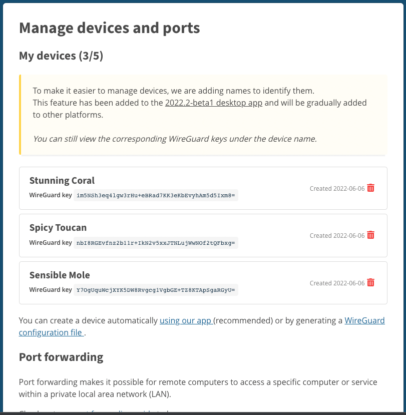
Once you have the private key from the Wireguard interface you'll need to login into Mullvad and browse to "My account" and then click on "Manage devices and ports". It should take you to a page that looks like the one shown below.
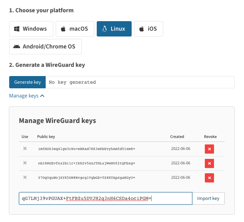
Next, you'll want to click on the "WireGuard configuration file" link. Your web page should look similar to the page below.
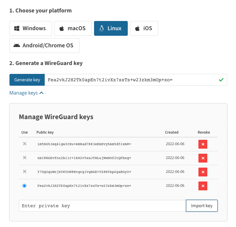
Next, you'll take the private key you saved from your Mikrotik configuration and import it. Once your private key is imported it should look similar to the image below. You can see that Mullvad created the public key from the private key.
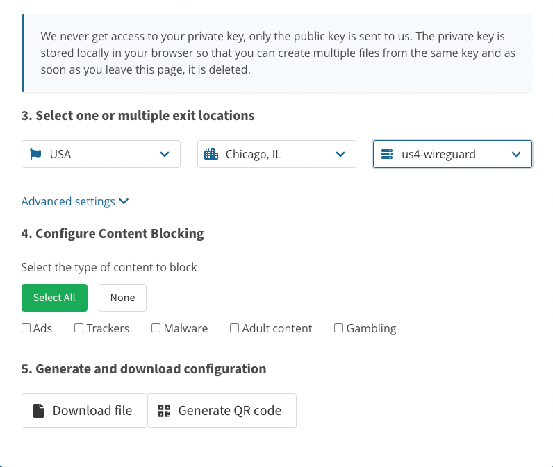
The next step is to scroll down and pick a server and other options you may be interested in. Once you picked your options you'll click "Download file" to retrieve the configuration needed to finish the peer configuration in the firewall.
Once the configuration is downloaded, open it in a text editor to retrive the rest of parameters to finish the Wireguard peer configuration. Below is an example of a configuartion file.
[Interface]
PrivateKey = qG7LMj39vPGUAX+FtFBZu5DVJH2q3nH6CSDa4ociPGM=
Address = 10.67.171.164/32,fc00:bbbb:bbbb:bb01::4:aba3/128
DNS = 10.64.0.1[Peer]
PublicKey = MRZsEblqO4wlq0WPnZgp5X9ex4Z2FHm9bljO/a/Mznk=
AllowedIPs = 0.0.0.0/0,::0/0
Endpoint = 68.235.43.82:51820
You'll need the Address, PublicKey, AllowedIPs and Enpoint information for the configuration below.
interface/wireguard/peers/add interface=Mullvad endpoint-address=68.235.43.82 endpoint-port=51820 allowed-address=0.0.0.0/0 public-key="MRZsEblqO4wlq0WPnZgp5X9ex4Z2FHm9bljO/a/Mznk="
ip/address/add interface=Mullvad address=10.67.171.164/32
The commands below are used to setup a routing table, NAT and a address list to assign specific IPs to be routing out of the firewall using the Mullvad VPN.
routing/table/add name=Mullvad fib
ip/route/add dst-address=0.0.0.0/0 gateway=Mullvad routing-table=Mullvad
The command below will allow you to specify which IPs you want to route out the Mullvad VPN.
ip/firewall/address-list/add list=Mullvad-VPN address=172.16.5.20
ip/firewall/mangle/add action=mark-routing chain=prerouting new-routing-mark=Mullvad passthrough=yes src-address-list=Mullvad-VPN
ip/firewall/nat/add action=masquerade chain=srcnat src-address-list=Mullvad-VPN
Wireguard Site to Site
The configuration below is an example of how I setup a site to site VPN using wireguard. I also included configuration on how to setup GRE and EoIP interfaces on top of the wireguard tunnel.
If you add a wireguard interface and don't specify the private key a new private key and corosponding public kill we be automatically generated for you. The public key is always used for remote peers to be able to encrypt data sent back to the interface. You'll see this in the example below. This this example I am using a 10.255.129.128/30 for my point-to-point network.
Site 1 configuration (Server)
Add the interface and choose a custom port if you're already using the default. The default MTU is 1420 but since I'll be stacking GRE on top I needed to make a little room for the GRE header.
interface/wireguard/add name=wg-IP32 listen-port=13232 mtu=1404
Next, I print out the interface to record the public key that I'll use in the peer configuration for site 2 (Client) configuration.
interface/wireguard/print
1 R ;;; Casselton to Fargo
name="wg-IP32" mtu=1404 listen-port=13232 private-key="<super_secret>" public-key="vc1sgmjS8k9t5UMZ+i+gDE9xjPZKCix/K9ksFCdASU4="
I have already create the interface for Site 2 (Client) ahead of time and copied the public key to put in the peer on Site 1 (Server) side configuration.
interface/wireguard/peer/add allowed-address=10.255.129.128/30 interface=wg-IP32 persistent-keepalive=25s public-key="chEwjsJhIXviZvzP98qvnqI9u/dtGWzjcGWT8ValKy8="
Now we need to add an IP to the wireguard interface.
ip/addressa/dd address=10.255.129.129/30 interface=wg-IP32
Since I'll be stacking services on top of wireguard I need a firewall rule to allow the IPs in the point-to-point network. Make sure you put this rule in the correct place in your firewall policy. You'll also need to create a firewall policy to let clients connect to your server side wireguard tunnel.
ip/firewall/filter/add action=accept chain=input dst-address=10.255.129.0/24 src-address=10.255.129.0/24
ip/firewall/filter/add action=accept chain=input connection-state=new dst-address=96.3.215.245 dst-port=13232 in-interface=WAN1 protocol=udp
The next command will create a GRE interface and stack it on top of our wireguard tunnel and assign an IP to it. The GRE interface provides a good layer 3 overlay to route and pass traffic.
interface/gre/add local-address=10.255.129.129 name=IPSec-GRE32 remote-address=10.255.129.130
ip/address/add address=10.255.128.129/30 interface=IPSec-GRE32
The last configuration for Site 1 (Server) side is a layer 2 EoIP interface to pass VLANs from site to site.
interface/eoip/add local-address=10.255.129.129 name=Designlogic-Casselton-EoIP remote-address=10.255.129.130 tunnel-id=32
Site 2 configuration (Client)
Add the interface and choose a custom port if you're already using the default. The default MTU is 1420 but since I'll be stacking GRE on top I needed to make a little room for the GRE header.
interface/wireguard/add name=wg-IP32 listen-port=13232 mtu=1404
Next, I print out the interface to record the public key that I'll use in the peer configuration for site 1 (Server) configuration.
interface/wireguard/print
Flags: X - disabled; R - running
1 R name="wg-IP32" mtu=1404 listen-port=13232 private-key="<super_secret>" public-key="chEwjsJhIXviZvzP98qvnqI9u/dtGWzjcGWT8ValKy8="
I have already create the interface for Site 1 (Server) ahead of time and copied the public key to put in the peer on Site 2 (Client) side configuration.
interface/wireguard/peers/add allowed-address=10.255.129.128/30 endpoint-address=96.3.215.245 endpoint-port=13232 interface=wg-IP32 persistent-keepalive=25s public-key="vc1sgmjS8k9t5UMZ+i+gDE9xjPZKCix/K9ksFCdASU4="
Now we need to add an IP to the wireguard interface.
add address=10.255.129.130/30 interface=wg-IP32
Since I'll be stacking services on top of wireguard I need a firewall rule to allow the IPs in the point-to-point network. Make sure you put this rule in the correct place in your firewall policy.
ip/firewall/filter/add action=accept chain=input dst-address=10.255.129.0/24 src-address=10.255.129.0/24
The next command will create a GRE interface and stack it on top of our wireguard tunnel and assign an IP to it. The GRE interface provides a good layer 3 overlay to route and pass traffic.
interface/gre/add local-address=10.255.129.130 name=IPSec-GRE32 remote-address=10.255.129.129
ip/address/add address=10.255.128.130/30 interface=IPSec-GRE32
The last configuration for Site 2 (Client) side is a layer 2 EoIP interface to pass VLANs from site to site.
interface/eoip/add local-address=10.255.129.130 name=Designlogic-Casselton-EoIP remote-address=10.255.129.129 tunnel-id=32